


Please Leave Us A Message
Privacy statement: Your privacy is very important to Us. Our company promises not to disclose your personal information to any external company with out your explicit permission.

 February 09, 2024

If any one or several of the batteries are allowed to be over-discharged, the performance of the rechargeable battery pack will deteriorate prematurely. When the battery pack is fully discharged, the ILOAD of the weakest section or batteries? The RINTERNAL voltage drop will exceed the internal VCELL chemical potential and the battery terminal voltage will change to a negative value (relative to the standard voltage). In this case, an irreversible chemical process will begin, changing the internal material properties that initially provided the charge storage capability of the battery, so that the subsequent charge cycle of the battery will not retain the original internal energy. In addition, once a battery is damaged, it is more likely to suffer a polarity reversal during subsequent use, which in turn causes problems to deteriorate and rapidly shortens the effective cycle life of the battery pack.
Excessive discharge of a series of tandem batteries does not necessarily pose a safety hazard when using a nickel-based battery chemistry, but one or more battery failures often occur long before the user perceives any significant drop in performance. The phenomenon of polarity reversal. It’s too late to fix the battery pack at that time. When using a chemical composition of a Lithium Battery with a higher energy storage density, polarity reversal must be prevented as a safety measure against overheating or fire. Therefore, it is absolutely necessary to monitor the voltage of each cell for ensuring long battery life (and safety when using a lithium battery).
Consider using the LTC6801, an integrated solution developed specifically to address these specific issues. The LTC6801 is capable of detecting overvoltage (OV) and undervoltage (UV) conditions in up to 12 serial battery cells and utilizing cascadable interconnects to handle extended device chains, all without the need for any micro Processor support.
Features of the LTC6801

The operating mode and programmable threshold levels are set by pin bonding. 9 UV settings (from 0.77V to 2.88V) and 9 OV settings (from 3.7V to 4.5V) are available. The number of monitored batteries can be set between 4 and 12, and the sampling rate can be set to one of 3 different speeds to optimize the relationship between power consumption and detection time. Three different hysteresis settings are also provided to accommodate the operating state of the alarm recovery function circuit.
To support an extended configuration of tandem cells, fault signaling is transmitted by bidirectional transfer of galvanically isolated differential clock signals in a "stacked" device chain, thus providing excellent immunity to load noise applied to the battery pack. Any device in the device chain that detects a fault will interrupt its output clock signal, so any fault indications in the entire device chain will propagate to the "end" device in the stack. The clock signal is generated by a dedicated IC (for example: LTC6906) or a master microprocessor (if one is needed) at the end of the stack and is cycled through the device chain when it is normal.
In many applications, the LTC6801 is used as a backup monitor for more sophisticated acquisition systems such as the LTC6802 (eg in hybrid vehicles). However, it is also ideal for stand-alone solutions for lower cost products such as portable tools and backup power. Since the LTC6801 draws its operating power directly from the battery it monitors, the available battery voltage range for each device changes due to the chemical composition of the battery and is designed to provide the voltage required to operate the device – from approximately 10V up to 50V or more . This voltage range supports stacking 4 to 12 cells of Li-Ion or 8 to 12 nickel cells in groups. As shown in Figure 1, it is very simple to use the LTC6801 to monitor a nickel battery pack (containing 8 nickel batteries) and protect it from over-discharge. Note that although only one undervoltage alarm is related to the chemistry of the nickel battery, due to the OV condition, the battery pack continuity fault will still be detected during the charging operation.
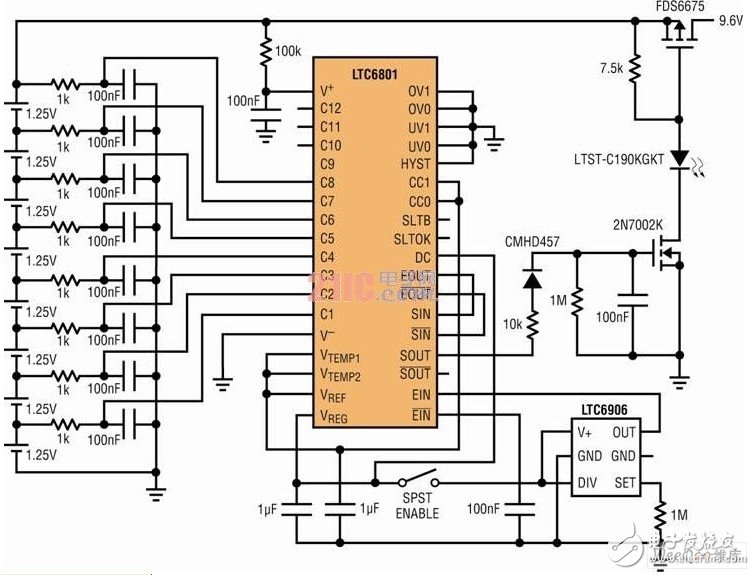
figure 1
Avoid battery reversalIn a battery pack of conventional nickel-based multi-cell batteries, battery reversal is a major mechanism of damage and can actually occur long before other significant charge depletion symptoms occur.
Take the following situation as an example. A battery pack with eight nickel-cadmium batteries (NiCd) is powering hand tools such as drills. Ordinary users will use the drill until its speed slows to about 50% of its initial speed, which means that the battery pack with a nominal voltage of 9.6V drops to about 5V after the loading operation. Assuming that the cells are fully matched (as shown in the sketch on the left side of Figure 2), it means that the voltage of each cell has been running as low as 0.6V, which is acceptable for each cell. However, if there is a mismatch in the battery (so that the voltage of the five cells may still be above 1.0V), the other three cells will have a voltage below 0V and experience a reverse stress, as shown in the center of Figure 2. The thumbnail is shown.
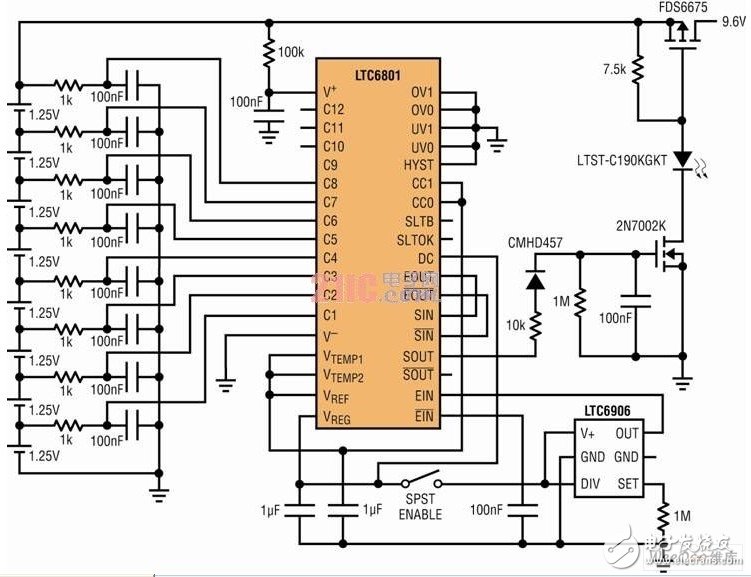
figure 2
Even if you assume that there is only one weak battery in the battery pack (a realistic situation), as shown in the right side of Figure 2, the first battery reversal is likely to be when the battery pack voltage is still 8V or higher. Occurs, but only the subtle battery pack's power supply capability is reduced. Due to the inevitable battery mismatch, the user will inadvertently reverse the battery periodically, thus reducing the capacity and life of the battery pack. Therefore, a circuit that can detect the exhaustion of a certain battery at an early stage can provide important value to the user.
Adopt LTC6801 solutionThe LTC6801's lowest available UV setting (0.77V) is ideal for detecting the exhaustion of nickel battery packs. Figure 1 shows a MOSFET switch that is used as a load disconnect device that is controlled by the output state of the LTC6801. When a battery is exhausted and its potential drops below the threshold, the load is removed, thus avoiding battery reversal and its performance degradation. It also allows safely obtaining maximum energy from the battery pack because no assumptions are made about the relative matching of the battery, and such an assumption may be required when using an overly conservative single cell potential threshold function.
A 10kHz clock is generated by the LTC6906 silicon oscillator and the LTC6801 output status signal is sensed and used to control the load disconnect action. Since this example does not involve stacking of devices, the cascadable clock signal is simply echoed back instead of being passed to another LTC6801. One LED is used to provide a visual indication of "power to the load." When the switch is open, the voltage of the weak battery tends to recover slightly, and the LTC6801 will restart the load switch (no hysteresis when using the 0.77V undervoltage setting). The rate of this digital load limiting action depends on the configuration of the DC pin; in the fastest response mode (DC = VREG), the duty cycle of the delivered load power drops and decrements to zero, while the weakest battery is safe When the ground reaches a fully discharged state, the pulsation becomes noticeable and slow.
In some applications, when the weakest battery is near full discharge (as shown in Figure 1), automatic interrupt loading is unacceptable. For these situations, the circuit shown in Figure 3 may be a good alternative. This circuit does not force some kind of load intervention, but simply provides an audible alarm indication that tells the battery that the battery is nearly exhausted. Here, the LED provides an indication that "the alarm circuit is in operation and there is no battery drain".
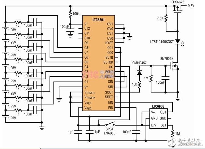
image 3
When the source clock is not present, an LTC6801 idle mode is invoked and the power dissipation is then reduced to a negligible 30μA, well below the typical self-discharge current of the battery pack. In both Figure 1 and Figure 3, the circuits shown have a switch that is responsible for deactivating the oscillator (and other peripheral circuits) to place it in idle mode when the circuit is not in use, thereby maximizing Reduce battery consumption.
in conclusionThe LTC6801 can simultaneously monitor up to 12 individual batteries in a multi-cell battery pack, maximizing battery pack capacity and life. Multiple LTC6801s can also be cascaded to support larger battery packs. The device is highly integrated, configurable, and well thought out, including an idle mode that minimizes battery pack consumption during inactivity. This makes the LTC6801 a compact solution for improving the performance and reliability of battery-powered products.
The above is the Battery-powered LTC6801 we have listed for you. You can submit the following form to obtain more industry information we provide for you.
You can visit our website or contact us, and we will provide the latest consultation and solutions
Send Inquiry
Most Popular
lastest New
Related Products
Send Inquiry
Privacy statement: Your privacy is very important to Us. Our company promises not to disclose your personal information to any external company with out your explicit permission.
Fill in more information so that we can get in touch with you faster
Privacy statement: Your privacy is very important to Us. Our company promises not to disclose your personal information to any external company with out your explicit permission.